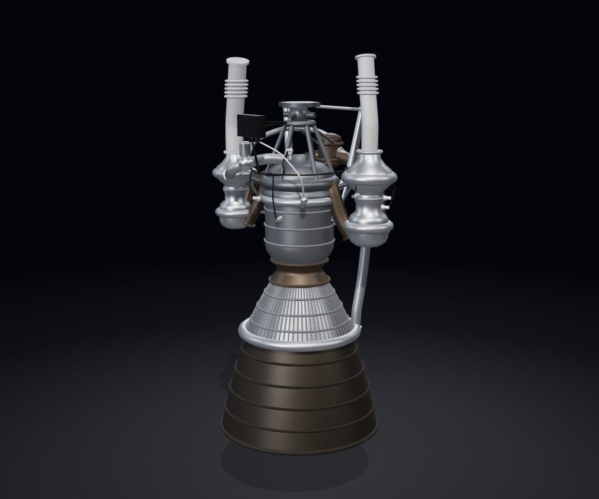
Next-Generation Rocket Engine Digital Twin
Design · Simulate · Test · Diagnose
Reusable Liquid Rocket Engine · Reference Architecture
Interactive digital-engineering learning environment for understanding propulsion systems, control, instrumentation, health monitoring and digital-twin behaviour.
Desktop / Laptop Experience
- REFERENCE MODEL
- SIMULATED
Engine · Turbomachinery
Turbomachinery · components
Choose a component to read about it.
Take the engine apart, or open a part to see inside.
Assembly
Cutaway
Follow what moves through the engine.
Choose a flow to see its path.
The engine controller reads these measurements. Trace one to see where it goes.
Chamber pressure
Primary thrust feedback for the control loop.
Pump discharge pressure
Shows the pressure the turbopump adds.
Turbine inlet temperature
Limit-monitored to protect the turbine.
Turbopump shaft speed
Overspeed protection and pump power estimate.
Turbopump vibration
Bearing and rotor condition.
Bearing temperature
Follows bearing wear, later than vibration.
Coolant outlet temperature
Shows the heat picked up from the wall.
Valve position
Confirms that each valve followed its command.
Thrust mount strain
Load carried from the engine into the vehicle.
Ready to run.
- System checkController self-test, sensor checks and confirmation of every valve position.
- ConditioningLines and pumps are chilled to propellant temperature so that liquid reaches the pump inlets.
- ReadyAll start conditions are met and the sequence waits for the start command.
- StartValves open in sequence, the igniter fires, the turbopumps spin up and chamber pressure rises.
- MainstageSteady operation at the commanded thrust and mixture ratio.
- ThrottleThrust is stepped down and back up to exercise the control loop.
- ShutdownValves close in sequence, the pumps spin down and the lines are purged.
- ReviewRecorded data is compared with expected behaviour and the health indicators are updated.
Start a fault scenario, then follow it from symptom to diagnosis to response.
No fault scenario is running. The engine is in its reference condition.
Set what the sensors report beside what the models expect.
Choose a view. The four digital twin states are defined further down the page.
How hardware, sensors, software, models and test evidence form one system.
- ENGINE HARDWARE
The physical engine: what everything else observes and commands. - SENSORS
Pressure, temperature, speed, vibration, position and strain. - DATA ACQUISITION
Conditions and digitises every sensor signal. - ENGINE CONTROL
Sequences the engine and commands the valves and actuators. - PHYSICS MODELS
Say what the engine should be doing for the same commands. - FDIR / HEALTH LOGIC
Detects a fault, isolates it and recommends a response. - DIGITAL TWIN
Holds observed, estimated, expected and predicted state together. - TEST EVIDENCE
What a simulated test shows about each requirement.
Understand a Rocket Engine as a Complete System
A liquid rocket engine is not one component but a set of systems that have to work together within tight margins. The Next-Generation Rocket Engine Digital Twin presents a reusable liquid rocket engine reference architecture as a complete system, so you can see how each part depends on the others.
The propellant feed system supplies the turbomachinery; the turbopumps deliver high-pressure propellants to the combustion chamber; regenerative cooling protects the chamber and nozzle; and the engine controller uses instrumentation to sequence, regulate and protect the engine. The same measurements feed engine health monitoring, fault diagnosis and the digital twin.
What the experience covers
- Propellant feed architecture
- Turbomachinery
- Combustion
- Regenerative cooling
- Nozzle operation
- Valves and actuation
- Instrumentation
- Engine control
- Simulated test sequences
- Health monitoring
- Fault diagnosis
- Digital-twin comparison
Explore the Engine
Rocket Engine Architecture
The reference architecture is a pump-fed, regeneratively cooled, throttleable and restartable liquid rocket engine with a closed cycle: the gas that drives the turbines is burned again in the main chamber. It is a teaching layout, not a design.
Propellant Feed System
Carries liquid oxidiser and fuel from the vehicle tanks to the turbopump inlets at the pressure and temperature the pumps need to run without cavitating.
Explore the propellant feed systemTurbomachinery
Turbopumps raise propellant pressure far above tank pressure; a turbine driven by hot gas supplies the shaft power.
Explore turbomachineryCombustion Chamber
The injector mixes the propellants and the chamber burns them at high pressure, turning chemical energy into hot gas.
Explore the combustion chamberRegenerative Cooling
Fuel flows through channels in the chamber and nozzle wall before it is burned, carrying heat away and keeping the wall within its temperature limit.
Explore regenerative coolingRocket Nozzle
A converging–diverging nozzle accelerates the hot gas to supersonic speed, converting pressure and temperature into thrust.
Explore the rocket nozzleValves and Actuation
Valves start, throttle and stop the propellant flows; actuators position the valves and steer the engine.
Explore valves and actuationRocket Engine Instrumentation
Pressure, temperature, speed, vibration, flow and position sensors measure what the engine is doing.
Explore rocket engine instrumentationEngine Control System
The engine controller sequences start and shutdown, holds thrust and mixture ratio at their commanded values, and shuts the engine down safely if a limit is exceeded.
Explore the engine control system
From Sensors to Digital Twin
Instrumentation turns engine behaviour into data. That data serves three purposes: control, protection and understanding the engine's condition.
Simulated Engine Testing
A Simulated Engine Test steps the reference engine through eight phases, showing what the controller does and what the sensors would report in each.
- System check
- Conditioning
- Ready
- Start
- Mainstage
- Throttle
- Shutdown
- Review
Engine Health Monitoring
Engine Health Monitoring watches for departures from expected behaviour. Each fault scenario in the experience shows a symptom, how it is diagnosed and how the engine responds.
- Turbopump bearing wear
- Cooling channel restriction
- Chamber pressure sensor drift
Digital Twin
The Digital Twin keeps four views of the engine side by side:
- OBSERVED
- Synthetic or imported telemetry: what the sensors report.
- ESTIMATED
- States inferred by the model, including quantities that no sensor measures directly.
- EXPECTED
- Reference-model behaviour for the same commands and conditions.
- PREDICTED
- Projected future behaviour, with uncertainty that widens with the prediction horizon.
Model Credibility
The experience uses reference and reduced-order models for interactive learning. Each model below identifies its fidelity, its main assumptions, its validation status and whether its data is simulated or correlated with external evidence. None of the models here is correlated with test data.
- REFERENCE MODEL
- SIMULATED
- REDUCED ORDER
- NOT TEST-CORRELATED
| Model | Fidelity | Assumptions | Data | Validation |
|---|---|---|---|---|
| Engine geometryREFERENCE MODEL | Illustrative layout, not to scale | Shows how the systems connect. Carries no dimensions, materials or tolerances. | REFERENCE MODEL | NOT TEST-CORRELATED |
| Engine cycle and performanceREDUCED ORDER | Steady state, lumped parameter | Normalised to a reference operating point. No transient combustion or two-phase flow. | SIMULATED | NOT TEST-CORRELATED |
| Simulated Engine TestSIMULATED | Scripted phase sequence | Phase order and intent are representative; timings are illustrative. | SIMULATED | NOT TEST-CORRELATED |
| Fault scenariosSIMULATED | Scripted symptom, diagnosis and response | Each scenario shows one fault in isolation. | SIMULATED | NOT TEST-CORRELATED |
| Digital Twin comparisonREDUCED ORDER | Single illustrative snapshot | Observed values are synthetic. Predicted values carry an illustrative uncertainty band. | SIMULATED | NOT TEST-CORRELATED |
Frequently Asked Questions
What is a rocket engine digital twin?
A rocket engine digital twin is a digital representation that combines an engine architecture, physics-based or data-driven models, simulated or measured telemetry, operating state and health information. It can be used to compare expected and observed behaviour, investigate anomalies and study how engine systems interact. The digital twin on this page is educational: its models are reference and reduced-order models, and its telemetry is simulated.
What can I explore in this 3D rocket engine?
You can explore a reusable liquid rocket engine reference architecture system by system: the propellant feed system, turbomachinery, combustion chamber, regenerative cooling, nozzle, valves and actuation, instrumentation and engine control. You can follow propellant, cooling, hot-gas and data flows, run a simulated engine test from system check to review, work through fault scenarios, and compare observed, estimated, expected and predicted digital twin states.
What is turbomachinery in a liquid rocket engine?
Turbomachinery is the rotating equipment that pressurises the propellants. A turbopump combines a pump and a turbine on one shaft: hot gas spins the turbine, and the turbine drives the pump. Pump-fed engines use turbopumps because raising propellant pressure at the engine lets the vehicle's tanks stay light and at low pressure while the combustion chamber runs at high pressure.
How does regenerative cooling work?
In regenerative cooling, one propellant, usually the fuel, flows through channels built into the wall of the combustion chamber and nozzle before it is burned. The propellant absorbs heat from the wall, which keeps the wall within its temperature limit, and carries that heat back into the engine cycle. Heat flux is highest near the throat, so cooling there is the most demanding.
What does the engine controller monitor?
The engine controller reads pressures, temperatures, turbopump shaft speeds, vibration, flow rates and valve positions. It uses them to sequence start and shutdown, to hold thrust and mixture ratio at their commanded values, and to check limits. If a critical measurement crosses its limit and redundant sensors confirm the reading, the controller reduces power or shuts the engine down.
How is engine health monitored?
Engine health monitoring compares what the sensors report with what a model expects for the same operating conditions. The differences, together with trends across runs and features such as vibration signatures, are used to detect a fault, isolate it to a component and estimate how it will progress. For a reusable engine, the result informs inspection and maintenance between flights.
What is the difference between a simulation and a digital twin?
A simulation runs a model of a system under chosen conditions. A digital twin is tied to a particular system: it takes that system's telemetry, estimates its current state and compares observed with expected behaviour over time. A simulation answers what would happen; a digital twin also answers what is happening and what is likely to happen next. Here, the telemetry is itself simulated.
Are the engine values shown here from a real flight engine?
No. The engine shown here is a reusable liquid rocket engine reference architecture created for digital-engineering education and simulation. Geometry, telemetry, operating states, faults and predictions are illustrative or simulated unless explicitly identified otherwise. It does not represent any production or flight engine, and the experience is not test-correlated.
Glossary
- Telemetry
- Measurements sent from the engine's sensors and controller for monitoring and recording.
- FDIR
- Fault detection, isolation and recovery: noticing that something is wrong, finding where, and acting to stay safe.
- Reduced-order model
- A simplified model that keeps the dominant physics so that it runs fast enough for interactive use.
- Model residual
- The difference between an observed value and the value a model expects for the same conditions.
- Mixture ratio
- The mass flow of oxidiser divided by the mass flow of fuel.
- Redline
- A limit on a measured quantity that, once exceeded and confirmed, triggers a protective action.
Designed By
Next-Generation Rocket Engine Digital Twin is an EV.ENGINEER™ interactive engineering experience.
Experience information last reviewed: .
Inspiration & Acknowledgement
Special thanks to Bhavya for inspiring our early approach to interactive engineering visualisation and Digital Twin experiences across Satellite Engineering, Model Rocketry and Aerospace.